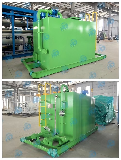
Atmospheric Gauge Tank
Atmospheric Gauge Tank is the vessel designed for temporal storing of the crude oil after the separation in the separator and surge tanks, used in onshore and offshore well testing operations.
General Introduction
Atmospheric Gauge Tank is the vessel designed for temporal storing of the crude oil after the separation in the separator and surge tanks, used in onshore and offshore well testing operations. Being the part of the well testing system, Atmospheric Gauge Vessel mainly used to measure the flow rate and calibrate liquid metering instruments of the test separator. Atmospheric Gauge Tank has inlet and outlet of the crude oil. Oil enters from the surge tank and emptied by the oil transfer pumps.
Atmospheric gauge tank consists of the enforced vessel to ensure proper storage, sight glasses (level gauges) to control oil level, flame arrestors on each vent of the vessel, a grounding strap, and shearing roof to prevent the vessel from overpressure. Nowadays, gauge tanks rarely used in offshore well test operations and replaced by the surge tank. Also, gauge tank is not used in areas where H2S is presented as this is hazardous to the operation personnel.
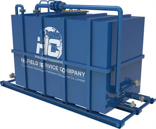
Our atmospheric gauge tanks are designed and manufactured for various volumes and pressures.
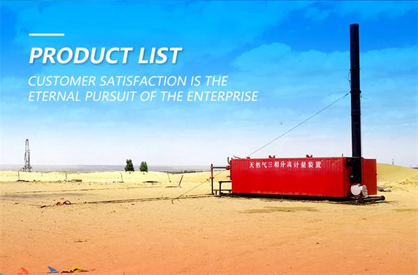
Application:
- Well Clean-ups
- Frack Flowback
- Well Testing
Technical drawings
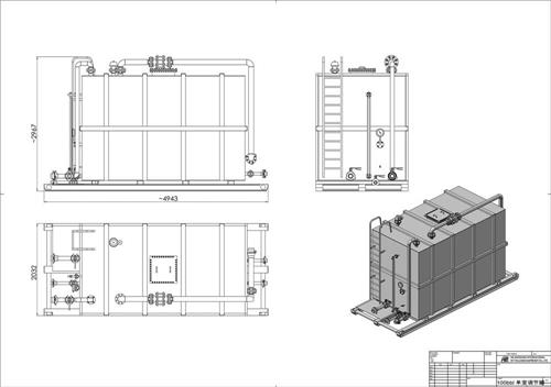
Technical Parameters
| HC Model Number | HCWT-GT-100-1 | HCWT-GT-210 | HCWT-GT-500 |
| Capacity | 100 bbl | 210 bbl | 500 bbl |
| Compartment Numbers | Single | Dual | Dual |
| Service | General | General | General |
| Pressure | 150 psi | 150 psi | 150 psi |
| Working Pressure | Atmospheric | Atmospheric | Atmospheric |
| Inlet | 3 inch ANSI 602 WECO | 3 inch ANSI 602 WECO | 3 inch ANSI 602 WECO |
| Outet | 3 inch ANSI 602 WECO | 3 inch ANSI 602 WECO | 3 inch ANSI 602 WECO |
| Drain | 3 inch ANSI 602 WECO | 3 inch ANSI 602 WECO | 3 inch ANSI 602 WECO |
| Code | API / ANSI | API / ANSI | API / ANSI |
| Weight | 7000 lbs. | 12100 lbs. | 21100 lbs. |
Process Principle
A metering skid is an integrated system designed for accurate measurement of oil, gas, or water in production and pipeline operations. Its principle is based on high-precision flow meters combined with temperature, pressure, and density sensors to convert and correct flow data. The system can be connected to automation and SCADA platforms for real-time monitoring and reliable data transmission.
Working Process
1.Inlet – The fluid enters the skid through the inlet line, passing filters and flow conditioners to ensure stable flow and remove impurities.
2.Measurement – The fluid flows through high-accuracy flow meters (such as turbine, Coriolis, or ultrasonic), while temperature and pressure sensors record real-time conditions.
3.Data Correction – The system integrates flow, temperature, pressure, and density data to automatically convert to standard conditions.
4.Data Processing – A PLC or flow computer processes the results, displays them locally, and transmits them to the control center or client system.
5.Outlet – After measurement, the medium continues through the outlet line to downstream facilities or pipelines without affecting normal transfer.