Test Separator
Test separators are used in well testing, well clean-ups and other flow operations for efficient and safe separation and efficient measurement of oil, gas and water.
Test Separator
Test separator is an indispensable device in the exploration and development of onshore and offshore oil and gas fields. It is mainly used in well testing, well clean-ups and other flow operations for efficient and safe separation and measurement of oil, gas and water. According to the form can be divided into horizontal, vertical and spherical.
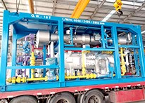
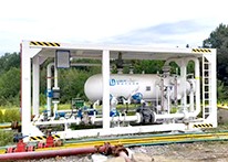
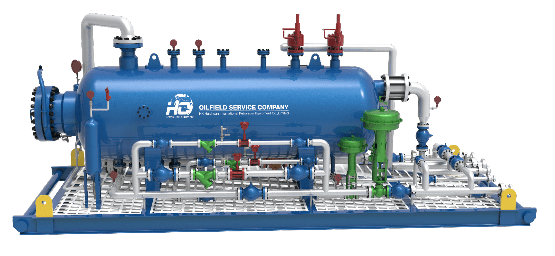
Our 3P Test Separators usually supplied with high-accuracy instruments, control and shut-off valves, piping and skid, and referred as Test Separator Package / Module / Skid. Separator vessel is equipped with internal components, such as inlet deflector, vane pack, coalescer, wave breaker, weir plates, and mist extractor. Separator modular unit can be used both in offshore or onshore, either in standalone item or part of the package, and designed to fit the trailer for ensure fast and effective mobility during operation.
Our company's test separator adopts pressure controller, level controller and pneumatic control valve to achieve automatic control of pressure and liquid level of the metering separator, which can meet the well test requirements of various oil and gas fields. At present, it has been widely used in Changqing, Dagang, Jilin, Qinghai, Daqing and other oil fields in China and overseas oil fields such as Egypt, Myanmar, Algeria, Nigeria, Russia, and India, and has achieved good economic and social benefits.
Our test separators are designed and manufactured in full compliance with international standards and are ASME certified. It has the following advantages:
- Our standardized products have excellent cost performance and currently cover 80% ~ 90% of domestic oil fields. They are also widely used in natural gas fields;
- Compact and reasonable structure design, integration of a variety of measuring instruments and control equipment;
- Compatible with multiple control modes (direct + PLC + computer + DCS);
- Multilevel security measures to ensure safe and reliable operation of the device;
- In addition to standard products, we can also customize the most suitable design for customers according to their needs;
- Reliable quality, which can be matched with components according to the customer's designated brand, such as instruments and valves;
- It can meet GB, ASME, API and other national and industrial specifications at the same time.
HC is committed to becoming an industry leader in oilfield equipment. Our facilities are certified with ISO, API and ASME standards. Feel free to contact us for efficient and economical solutions.
Test Separator Working Process
Feature
- Special design and certification for offshore operations.
- Modular skid for onshore operation.
- Durable internals .
- Certified and reliable flow control valve and instruments .
- Instrument gas scrubber .
- Sample points for oil, gas, water and inlet medium.
- High / Low alarm points and pressure relief valves.
Code & Standards
- ASME Section VII, DIV 1
- NACE MR0175
- API 12J
- UL, Exp
- PED
- CE
- API 6A, API 6D
- ANSI B31.3 Class M (H2S)
Application
- Exploration well testing
- Extended well testing
- Clean-ups and flowback operations
- Multiphase flow metering
Horizontal Separator / Vertical Separator
According to the installation mode, the separator can be divided into horizontal/vertical installation, or indoor/outdoor installation.
The horizontal separator is built horizontally, in other words, as the vessel shell axis parallel to the ground. It is usually used for large liquid/gas ratio fluid treatment or liquid/liquid separation. Compared with vertical separators, there are longer horizontal sections for liquid flowing and shorter vertical sections for gravity separation of liquids with different densities. The horizontal separator requires a relatively large horizontal installation space, and its application is generally not affected by the field wind.
Horizontal separator can be used for test separator, production separator, two-phase separator, three-phase separator and special application separator.
The vertical separator is built vertically, which means the vessel shell axis is perpendicular to the ground. It is usually used for large gas/liquid ratio fluid treatment. Compared with horizontal separators, there are larger cross-sectional area for gas flowing and longer vertical sections for gravity separation of liquids from the gas. The vertical separator requires a relatively small horizontal installation space, but for very high or slender separator the field wind shall be considered.
Vertical separator can be used for test separator, production separator, two-phase separator, three-phase separator and special application separator.
Test Separator Basic parameters
Separator can be designed as per client’s operation conditions depending on flowrate, temperature, pressure, working medium and other operation data. Most of the clients, prefer size of 42 in. x 10 ft. and pressure of 1440 psi, for well test operation.
| Design pressure | Vessel size | Liquid Capacity | Dimensions(L x W x H) | Dimensions(L x W x H) | |||
| psi | bar | Mpa | inch x foot | cm | BOPD | ft | m |
| 800 | 55 | 5.5 | 34x8 | 86x244 | 3500 | 13x7x8.5 | 4.0x2.1x2.6 |
| 1440 | 99 | 10(9.93) | 30x10 | 76x305 | 3500 | 15x6.5x8 | 4.6x2.0x2.5 |
| 42x10 | 107x305 | 10000 | 15x7.5x9 | 4.6x2.3x2.7 | |||
| 42x15 | 107x457 | 12000 | 20x7.5x9 | 6.1x2.3x2.7 | |||
| 48x10 | 122x305 | 13000 | 15x8x9.5 | 4.6x2.5x2.9 | |||
| 48x12 | 122x366 | 19000 | 17x8x9.5 | 5.2x2.5x2.9 | |||
| 48x15 | 122x457 | 19000 | 20x8x9.5 | 6.1x2.5x2.9 | |||
| 2160 | 149 | 15(14.9) | 24x10 | 61x305 | 1000 | 15x4x7.5 | 4.6x1.2x2.3 |
| 42x15 | 107x457 | 12000 | 20x7.5x9 | 6.1x2.3x2.7 | |||
| 48x15 | 122x457 | 15000 | 20x8x9.5 | 6.1x2.5x2.9 | |||
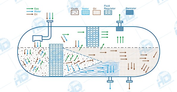
Process Principle of Oil-Gas-Water Three-Phase Separator
During oil and gas production, the extracted fluid from the wellhead is not a single stream of oil or gas, but rather a complex mixture composed of crude oil, natural gas, and water. To enable subsequent processing and utilization, these three components must be efficiently separated, which is achieved using a three-phase separator.
1. Working Principle
The three-phase separator mainly relies on gravity settling, fluid dynamics, and interface control to achieve the separation of oil, gas, and water:
- Gas Separation: After the mixed fluid enters the separator, the flow velocity decreases sharply. Due to its lowest density, natural gas rises quickly and is directed to the upper gas outlet.
- Liquid Stratification: The denser water settles at the bottom of the vessel, while the lighter crude oil floats above the water layer, forming a clear oil-water interface.
- Interface Control: With the aid of level gauges and interface controllers, the oil, gas, and water phases remain stably stratified inside the separator and are discharged separately through their respective outlets.
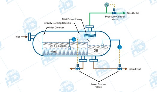
2. Main Structural Components
A standard three-phase separator is typically composed of the following parts:
- Shell (Pressure Vessel): Designed in horizontal or vertical orientation according to process requirements, generally cylindrical in shape, with pressure-resistant and corrosion-resistant properties.
- Inlet Device (Feed Distributor): Distributes the high-velocity mixed fluid evenly and reduces impact.
- Gas Separation Section: Located at the upper part of the vessel, often equipped with a demister or cyclone separator to remove liquid droplets entrained in the gas.
- Liquid Settling Section: Located at the middle and lower part, where oil and water are separated by gravity.
- Baffles / Coalescing Devices: Extend the retention time of liquids, promoting the coalescence and settling of small droplets.
- Interface Control System: Includes level gauges, interface sensors, and automatic liquid discharge control valves to maintain stable stratification of oil and water.
- Outlet Piping: Separate outlets are provided for the gas phase, oil, and water.
3. Working Process
- Feed Diffusion: The mixed fluid enters through the inlet, and its flow rate drops sharply, causing most of the gas to immediately escape.
- Preliminary Gas-Liquid Separation: The gas enters the upper space, passes through a demister to remove entrained liquid droplets, and is discharged through the gas outlet.
- Oil-Water Stratification: Under gravity, the liquid naturally separates—water, being denser, settles at the bottom, while oil floats on top.
- Interface Control: The oil-water interface height is maintained by a level control system to ensure stable separation.
- Three-Phase Discharge: Gas, crude oil, and wastewater are discharged separately through their respective outlets and sent to subsequent processing stages.
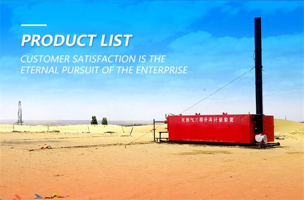
Project Cases