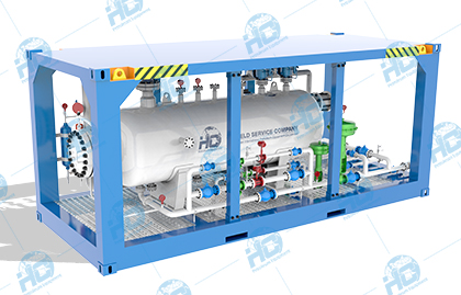
Three-phase Separator
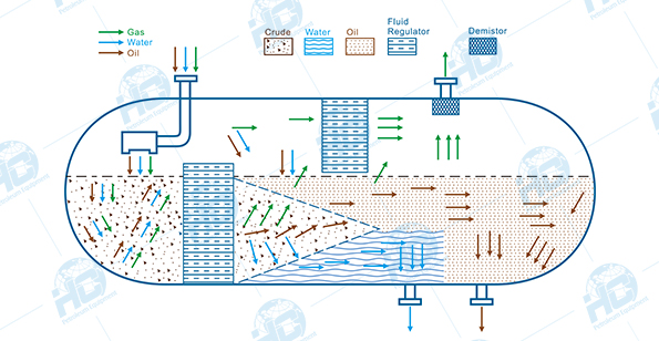
Three-phase separator is a basic component of petroleum production system, which is used to separate reservoir fluid from oil, gas and water. Then these separated flows are transported to the downstream for processing.
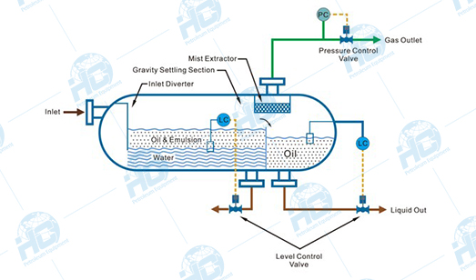
In general, a mixed fluid can be considered as a small amount of liquid A or/and gas B dispersed in a large amount of fluid C. In this case, the dispersed liquid A or gas B is called the dispersed phase, while the large continuous fluid C is called the continuous phase. For gas-liquid separation, it is sometimes necessary to remove tiny droplets of liquid A and C from large amount of gas B, where gas B is the continuous phase, and liquid A and C are the dispersed phases. When only one liquid and gas is considered for separation, it is called a two-phase separator or a liquid-gas separator.
The basic principle of separator is gravity separation. By making use of the density difference of different phase states, the droplet can settle or float freely under the combined force of gravity, buoyancy, fluid resistance and intermolecular forces. It has good applicability for both laminar and turbulent flows.
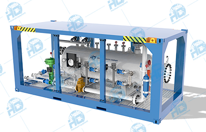
Our three-phase separator adopts advanced technologies of effective separation,throttling,automatic control,comprehensive anti corrosion and skid-mounted structure,and has the characteristics of high separating effeciency,high automation,stability,high measurement precision and accurate data details.
- In addition, our three-phase separator has the following advantages:
- 1.Compact and reasonable structure design, integration of a variety of measuring instruments and control equipment;
- 2.Compatible with multiple control modes (direct + PLC + computer + DCS);
- 3.Multilevel security measures to ensure safe and reliable operation of the device;
- 4.In addition to standard products, we can also customize the most suitable design for customers according to their needs;
- 5.Reliable quality, which can be matched with components according to the customer's designated brand, such as instruments and valves;
- 6.It can meet GB, ASME, API and other national and industrial specifications at the same time.